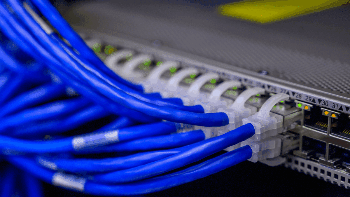
Network, network, and network again. This is technically the second side article on TCP/IP handshake, but honestly, it stands on its own, because the OSI model is way bigger than anything we’ve covered so far.
We’ve already gone through IP, TCP, and the TCP handshake. Now we’re stepping back from the Transport Layer and looking at the bigger picture: the OSI model.
Existence of OSI
The title is a bit dramatic, maybe even philosophical, but understanding why OSI exists in the first place is worth the detour.
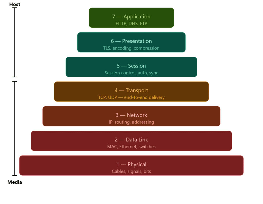
The OSI model divides networking into 7 layers. Instead of handling all types of communication in one place, each layer has a specific responsibility, this is what keeps networking manageable and organized.
Before we dive in, we’ve already been working inside the OSI model without naming it. TCP lives in the Transport layer (Layer 4), and IP lives in the Network layer (Layer 3). Protocols are just tools that belong to a layer, think of layers as the job title and protocols as the people doing the work.
As you go down the stack, you move closer to the physical connection. The upper layers (Host) deal with how data is structured and communicated between applications. The lower layers (Media) deal with how data actually moves across a network: cables, signals, hops.
The Network layer is where that transition becomes visible. IP is what decides the next hop, and each hop can run on a different medium. That’s exactly what we touched on in the TCP and IP article: your packet leaves your device over WiFi, hits your home router, and from there travels through fiber optic cables across your ISP’s infrastructure.
The 7 Layers
I’d love to cover every layer with working code, but this article is already pushing its limits and 7K words is not where I want to take it.
That said, the layers won’t stay theoretical for long. Dedicated articles are coming that put each layer into practice; Host layers in Python, Media layers in C++.
Python is natural for the upper layers where you’re dealing with protocols and application logic, C++ is the right tool once you get close to the hardware.
C++ isn’t a traditional low level language, but it’s capable of everything C (a low level language) is, and when it comes to low level tasks, it handles them just as well.
Application Layer
The Application layer is the topmost layer of the OSI model: Layer 7. It’s where end-user applications interact with the network directly.
HTTP, DNS, and FTP all live here. If you’re making a web request, resolving a domain, or transferring a file, you’re at the Application layer.
It’s the closest layer to the user, which means by the time data reaches here, everything below has already done its job: routing, ordering, error checking, all of it. The Application layer doesn’t worry about how the data got there. It just hands it to the application and lets it do its thing.
Presentation Layer
The Presentation layer is Layer 6. Its job is to make sure data is in a format both sides of the communication can actually understand.
Think of it as a translator. The application above doesn’t care about encoding or compression, it just wants the data. The Presentation layer handles the conversion before passing it up or down the stack.
Three things happen here: encoding (converting data into a readable format), encryption (TLS lives here: this is where HTTPS gets its S), and compression (reducing data size before transmission to save bandwidth).
When you visit an HTTPS site, the Presentation layer is what negotiates the TLS handshake and encrypts your data before it leaves your machine. The Application layer above it just sees clean, readable data, it never deals with the encryption directly.
Session Layer
The Session layer is Layer 5. It manages the lifecycle of a connection: opening it, maintaining it, and closing it cleanly.
When two devices communicate, they need more than just a reliable data transfer. They need a session: a structured conversation with a defined start and end. That’s what this layer handles.
Three things happen here: establishment (initiating the session between two endpoints), synchronization (adding checkpoints to long transfers so if something breaks midway, it can resume from the last checkpoint rather than starting over), and termination (closing the session cleanly once communication is done).
When you log into a website, the Session layer is what keeps you logged in as you navigate between pages. Without it, every click would be a brand new connection with no memory of who you are.
It’s worth noting that in modern web development, session management is often handled at the Application layer through cookies and tokens rather than at Layer 5 directly.
In practice, TCP bleeds into Session territory, a TCP connection has a defined start (the handshake), a maintained state, and a clean termination. That’s session behavior, just happening at Layer 4.
This is why in real implementations like the TCP/IP stack, Layers 5 and 6 are often barely distinguishable from Layer 7.
Transport Layer
We’re back to the Transport layer, but there’s not much to cover here since we have a dedicated article for it. What I can say is this layer is where the heavy lifting happens.
Segmentation, ordering, error checking, retransmission; all of it lives here. TCP and UDP are both Transport layer protocols, and they represent the two approaches this layer can take: reliable and ordered, or fast and loose.
Simply put, it’s the layer that makes sure data actually gets from one end to the other in one piece. Everything above it assumes it did its job correctly.
→ If you haven’t read the TCP and IP article, that’s the deep dive on this layer.
Network Layer
The Network layer is Layer 3, and this is where IP lives; which means we have a dedicated article for this one too.
Its job is addressing and routing. Every device on a network has an IP address, and the Network layer is what uses that address to get your data from one machine to another. It doesn’t care about order, reliability, or whether the data arrived correctly; that’s TCP’s problem up in Layer 4. It just moves packets.
The key concept here is routing. Your packet doesn’t travel directly from your machine to its destination. It hops through routers, and each router reads the IP header, checks its routing table, and forwards the packet to the next hop. It only knows the next step, not the full path.
This is also the layer where the physical medium starts to matter. Each hop can run on a different medium, your first hop to your home router is wireless, after that it’s fiber. The Network layer doesn’t care which, it just hands the packet down and lets the layers below figure out the physical details.
Data Link Layer
The Data Link layer is Layer 2. Where the Network layer handles logical addressing (IP), the Data Link layer handles physical addressing : MAC addresses. Every network interface card has a MAC address, and that’s what this layer uses to identify devices on a local network.
Two things happen here: framing (wrapping packets into frames the physical medium can transmit) and error detection (spotting corrupted frames and discarding them; not fixing, just detecting).
This is also where switches live. A switch reads MAC addresses to forward frames only to the intended device. Routers work at Layer 3, switches at Layer 2, a distinction worth knowing.
Physical Layer
The Physical layer is Layer 1: the bottom of the stack. This is where data stops being ones and zeros and becomes actual physical signals: electrical pulses over copper, light over fiber, radio waves over WiFi.
It doesn’t know anything about MAC addresses, IP addresses, or packets. It just transmits raw bits from one point to another. Everything above it handles the meaning of data, this layer just moves it.
Cables, network interface cards, switches at the hardware level, radio frequencies, all of that lives here. If something is broken at this layer, nothing above it works. It’s the foundation everything else is built on.
Encapsulation
Wrap the data, pass it to the next layer, repeat. That’s encapsulation at its core, and yes, it has a fancy name for a reason.
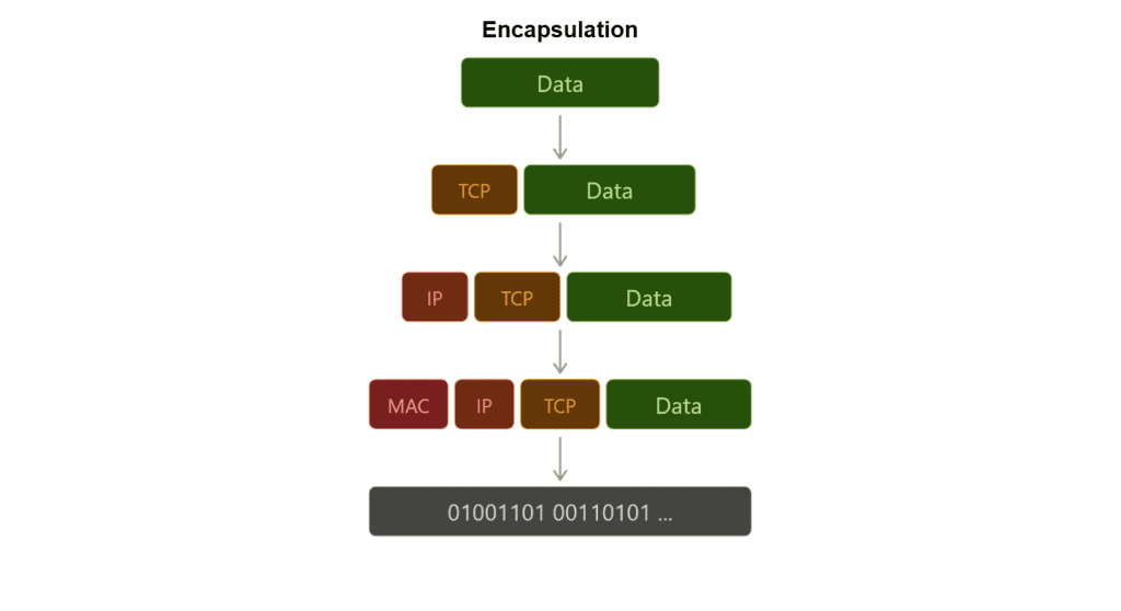
Every layer has its own job, but data still needs to travel through all of them. The way it does that is by getting wrapped at each layer with a header containing the information that layer needs to do its job. By the time your data reaches the Physical layer, it’s been wrapped multiple times, each layer added its own envelope on the way down.
On the sending side, data moves down the stack. The Application layer passes it to Presentation, Presentation to Session, and so on. Each layer wraps it with a header before handing it down. This is encapsulation.
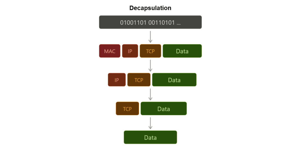
On the receiving side, the opposite happens. Data moves up the stack and each layer strips its own header, reads what it needs, and passes the rest up. This is decapsulation.
Each layer only reads its own header, it doesn’t care about what’s inside. The Network layer reads the IP header and forwards the packet. It doesn’t look at the TCP segment inside, that’s Layer 4’s job. This separation is exactly what makes the OSI model work.
This is exactly what we did with Scapy in the handshake article. When we wrote IP(dst=ip) / TCP(...), we were encapsulating a TCP segment inside an IP packet, wrapping a Transport layer packet into a Network layer envelope.
Worth noting: Layers 5 and 6 are sometimes skipped entirely in real implementations. In the TCP/IP stack for example, encapsulation effectively goes Application → Transport → Network → Data Link → Physical. The model is a framework, not a strict checklist.
Debugging the Network
The OSI model is a debugging map. Each layer gives a different result when it breaks, and that result tells you exactly where to look.
Physical: Nothing works at all. No connection, no signal. Check the cable, the port, the hardware.
Data Link: Devices on the same network can’t see each other. MAC address issues, switch misconfiguration.
Network: You can ping locally but not remotely. Routing problem, wrong subnet mask, or a misconfigured gateway. traceroute lives here, it shows you exactly which hop is dropping your packet.
Transport: The host is reachable but the service isn’t responding. Port closed, firewall blocking, wrong protocol. This is where your SYN goes unanswered and you get RST back, exactly what we saw in the handshake article.
Session / Presentation: Connection drops mid-transfer, TLS handshake fails, encoding mismatch. Usually shows up as a certificate error or a garbled response.
Application: Everything below works fine but the app throws an error. Wrong endpoint, malformed request, authentication failure. The network did its job, the problem is in the code.
Conclusion
Almost 2K words again, but this wraps up the last side article for the handshake series. Now we can move forward to the Packet Flow article.
There’s still a lot of work ahead. The Transport layer needs a proper practical breakdown, and every other layer is waiting for its own dedicated article.
Next up: Connection Between Client and Server: Packet Flow and Forgetting the Handshake: Transporting Data with UDP in Scapy.