Encoding characters was a first step toward building software with text, and with text, we can already make a console game. But why stop there? Games deserve images too, and to render those images, we need to understand how they’re encoded.
You might wonder why a security blog talks about games to explain a low-level systems concept. The answer is simple: games are what many people love, and they’re an excellent way to explain these ideas without overwhelming the reader.
In this article we start with pixels, move to color representation, then cover how images are stored and how compression saves space.
You can find the scripts used in this article in my GitHub repository.
A Pixel
A pixel is our starting point for encoding images. The word itself is short for picture element, the smallest unit we can use to represent an image on a digital display.
Each pixel holds two key pieces of information: a color and a brightness value.
Think of a pixel as a single tiny colored dot. On its own, it means nothing. But when you place thousands of them together, they form a grid, and that grid becomes an image.
Every pixel has a position defined by coordinates. A pixel at (3, 5) sits at column 3, row 5 on that grid, with (0, 0) typically being the top-left corner. By assigning different colors to different positions, you can construct anything from a simple shape to a full scene.
This grid of pixels is called a bitmap, literally a map of bits. The more pixels you pack into a given space, the higher the resolution and the sharper the image.
Before we go further with examples, let’s move on to color representation, it ties closely to pixels and you need to understand it before going any deeper.
Color representation
Every color you see on a screen is built from three channels: red, green, and blue : RGB. Your monitor doesn’t mix paint; it mixes light. Set all three to zero and you get black. Max all three out and you get white. Everything else is a combination in between.
Each channel holds a value from 0 to 255. That range exists because each channel gets 8 bits of storage, and 8 bits can represent 256 distinct values (2⁸ = 256) – I hope you remember.
Three channels at 8 bits each gives you 24-bit color, and 256 × 256 × 256 works out to about 16.7 million possible colors. That’s what people mean when they say “16 million colors.”
So a pixel with RGB(255, 0, 0) is pure red. RGB(0, 0, 255) is pure blue. RGB(255, 165, 0) is orange. Every color on your screen is just three numbers.
Alpha Channel
Sometimes three channels aren’t enough. When you need transparency, like a PNG logo on a website or a sprite in a game, you add a fourth channel: alpha.
Alpha works the same way, 0 to 255, where 0 is fully transparent and 255 is fully opaque. This gives you RGBA, 32 bits per pixel total.
Think of alpha as how much you let the background bleed through. A value of 128 means the pixel is half-transparent, you see 50% of the pixel’s color and 50% of whatever is behind it.
Alternative Color Models
RGB isn’t the only way to represent color. Depending on what you’re doing, other color spaces make more sense.
HSL stands for hue, saturation, and lightness. Instead of mixing channels, you describe color the way humans think about it, hue is the actual color (red, blue, green), saturation is how vivid it is, and lightness is how bright.
This is why graphic tools let you drag a slider to pick a color instead of typing three numbers. HSL is friendlier for humans; RGB is friendlier for machines.
YCbCr splits color into luminance (Y : brightness) and chrominance (Cb and Cr : color information). It exists because human eyes are much more sensitive to brightness differences than to color differences. Video formats and JPEG compression exploit this : they store brightness at full resolution but compress the color data more aggressively, and you barely notice. We’ll come back to this when we get to compression.
CMYK is for print. Screens emit light so they mix red, green, and blue. Printers absorb light so they mix cyan, magenta, yellow, and black (the K stands for key, meaning black). The logic is inverted, more ink means darker, less ink means lighter. If you’ve ever exported a design for printing and the colors came out wrong, it’s usually because you forgot to convert from RGB to CMYK.
If YCbCr and CMYK seem confusing, that’s completely normal, I had to read the docs three times before writing this. But I found a way to explain them that actually makes sense, so here it is:
Details : YCbCr
Y is luminance: brightness. YCbCr isn’t unique in having it; almost every color model carries some concept of brightness because human eyes detect light intensity before color.
The key thing about YCbCr is that brightness is separated from color entirely. That split gives you two distinct parts: luminance (Y) and chrominance (Cb and Cr).
Cb is the blue-difference channel. Cr is the red-difference channel. Increase Cb and the color shifts toward blue; decrease it and it shifts toward yellow. Increase Cr and it shifts toward red; decrease it and it shifts toward cyan.
You probably noticed something: there’s no green channel. And yet green exists on your screen. Here’s the trick, green is implicit. If you set Cb low (not much blue) and Cr low (not much red), what’s left over is green. You control how bright that green appears by adjusting Y. In other words: don’t push red, don’t push blue, set your brightness, and green shows up.
Want yellow? Yellow is red plus green. Increase Cr to bring in red, decrease Cb to suppress blue, set Y to your target brightness. The green is already implied by the absence of the other two.
So yes, you can describe every color without a dedicated green channel.
Now you might wonder: if YCbCr is so efficient, why do screens still use RGB? Because at the hardware level, RGB directly matches how displays actually work. Every pixel on your screen physically consists of three subpixels: one red, one green, one blue. The display can take RGB values and drive those subpixels directly with no conversion. YCbCr needs decoding into RGB before the display can do anything with it. It wins on storage and transmission, but RGB wins at the point where data meets hardware.
Details : CMYK
CMYK works on a completely different principle than RGB or YCbCr, and that’s because it’s built for printing, not screens.
Screens emit light. Printers absorb it.
When you mix red, green, and blue light together you get white, that’s additive color. When you mix inks together they absorb more and more light, giving you darker results, that’s subtractive color. CMYK is a subtractive model.
The four channels are cyan, magenta, yellow, and black (K : short for “key”).
C absorbs red light. So adding cyan to white paper removes red, shifting the color away from red.
M absorbs green light. Add magenta and green disappears from the mix.
Y absorbs blue light. Add yellow and blue drops out.
In theory, mixing cyan, magenta, and yellow at full strength should give you black, you’ve absorbed red, green, and blue, so no light reflects back.
In practice it gives you a muddy dark brown. Inks aren’t perfect, and combining three expensive color inks to approximate black is wasteful. So K exists, pure black ink, cheaper and cleaner.
Want red? Red is what’s left when green and blue are absorbed. So increase M (absorbs green) and increase Y (absorbs blue), leave C at zero. Red appears.
Want green? Increase C (absorbs red) and increase Y (absorbs blue), leave M at zero. Green appears.
The logic is always the same: you’re not adding color, you’re subtracting what you don’t want.
Demonstration
Let me show you how to draw a single pixel in RGB color format in a C++ application, because a live demo beats explaining it over text any day.
For this case, we’ll use raylib, it’s the simplest option available. It’s a graphics library that gives us direct access to pixel-level drawing.
#include "raylib.h"

int main() {
    InitWindow(400, 400, "pixel");

    while (!WindowShouldClose()) {
        BeginDrawing();
        ClearBackground(BLACK);

        DrawPixel(200, 200, WHITE);

        EndDrawing();
    }

    CloseWindow();
}Here we initialize a 400×400 window with the title “pixel”, then start a loop to keep it open. WindowShouldClose() returns true when the user closes the window or presses Escape.
Inside the loop, we call BeginDrawing() to start the frame, clear the background to black, then draw a single white pixel at the center coordinates (200, 200). EndDrawing() finalizes and presents the frame.
Now let’s do the same thing, but instead of using a named color constant like WHITE, we’ll construct the color manually using RGB values.
#include "raylib.h"

int main() {
    InitWindow(400, 400, "pixel");

    while (!WindowShouldClose()) {
        BeginDrawing();
        ClearBackground(BLACK);

        // Red
        DrawPixel(200, 200, (Color){255, 0, 0, 255});

        EndDrawing();
    }

    CloseWindow();
}One thing worth understanding: without the loop, the window would close immediately.
The loop isn’t just keeping the window alive, it’s continuously redrawing the frame, tens or hundreds of times per second.
So it’s not a static image sitting on screen; it’s the same pixel being drawn over and over. Think of it as a render loop.
Second Practice
Why stop here? Let’s do something more interesting, we’ll write “Ryuru” on the screen.
#include "include/raylib.h"
#include <string.h>

constexpr int COLS = 200;
constexpr int ROWS = 200;

int grid[ROWS][COLS] = {0};

int R[7][5] = {
    {1, 1, 1, 1, 0},
    {1, 0, 0, 0, 1},
    {1, 0, 0, 0, 1},
    {1, 1, 1, 1, 0},
    {1, 0, 1, 0, 0},
    {1, 0, 0, 1, 0},
    {1, 0, 0, 0, 1}
};

int Y[7][5] = {
    {1, 0, 0, 0, 1},
    {0, 1, 0, 1, 0},
    {0, 0, 1, 0, 0},
    {0, 0, 1, 0, 0},
    {0, 0, 1, 0, 0},
    {0, 0, 1, 0, 0},
    {0, 0, 1, 0, 0}
};

int U[7][5] = {
    {1, 0, 0, 0, 1},
    {1, 0, 0, 0, 1},
    {1, 0, 0, 0, 1},
    {1, 0, 0, 0, 1},
    {1, 0, 0, 0, 1},
    {1, 0, 0, 0, 1},
    {0, 1, 1, 1, 0}
};

void draw_char(int glyph[7][5], int ox, int oy) {
    for (int y = 0; y < 7; y++) {
        for (int x = 0; x < 5; x++){
            if (glyph[y][x]) grid[oy + y][ox + x] = 1;
        }
    }
}

int main() {
    InitWindow(COLS, ROWS, "Ryuru");

    int (*letters[5])[5] = {R, Y, U, R, U};
    for (int i = 0; i < 5; i++){
        draw_char(letters[i], 10 + i * 6, 10);
    }

    while (!WindowShouldClose())
    {
        BeginDrawing();
        ClearBackground(BLACK);

        for (int y = 0; y < ROWS; y++)
        {
            for (int x = 0; x < COLS; x++)
            {
                if (grid[y][x])
                    DrawPixel(x, y, WHITE);
            }
        }

        EndDrawing();
    }

    CloseWindow();
    return 0;
}We define three 7×5 arrays: R, Y, and U, where each one is just a bitmap of a letter made of 1s and 0s.
To get those coordinates, you can use an online pixel font editor like Piskel or pixilart.com, draw your letter on a small 5×7 canvas, and read off the grid. But honestly just ask an AI to generate the arrays for you, it’s not meaningful work to do by hand in 2026.
We also have a 200×200 grid that represents the screen, all initialized to 0.
drawChar takes a letter and a position, then stamps it onto the main grid by looping through the 7×5 pattern and marking the corresponding cells as 1 wherever the letter has a lit pixel.
In main, we open the window, then put our five letters : R, Y, U, R, U into an array and loop through them, placing each one 6 columns apart so they don’t overlap.
The render loop runs every frame, goes through every pixel on the screen, and draws it white if the grid says 1 or black if it says 0.
Pixels, Bitmaps & Color Models
Let’s gather everything up, because after the demonstration some of this can get confusing.
A pixel is the smallest unit on a screen. One dot, one color.
A bitmap is just a grid of pixels where you control which ones are on and what color they are.
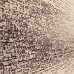
Now, bitmap vs grid.
A grid is a structure, rows and columns of cells each holding a value. A bitmap is a grid where each cell is specifically a pixel with a color.
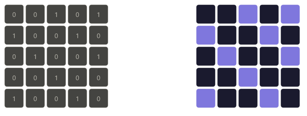
On the left side of the image is a grid, and on the right side is a bitmap.
So every bitmap is a grid, but not every grid is a bitmap. In our code, the grid array is just integers. It becomes a bitmap the moment we map those values to colors.
Hope that clears it up.
Color is just three numbers, red, green, blue, each ranging from 0 to 255. Mix them and you get any color you want. Raylib gives you shortcuts like WHITE or RED but they’re just preset RGB values under the hood.
A pixel grid is exactly what it sounds like. A 2D array where each cell maps to a pixel on screen.
Storing Images
Now that we understand pixels and color, we can talk about how images actually get stored. When you save an image to disk, something has to convert that grid of colored pixels into bytes. Let’s look at how that works.
Raster vs vector
There are two fundamental ways to store an image.
A raster image stores color values for every single pixel in the grid. What you see is what’s saved, a fixed-width, fixed-height map of colored dots.
So yeah, it basically stores every pixel in the grid, row by row, left to right. Just raw color values written out one after another.
Photos, screenshots, and anything rendered from a game are raster images. The downside is that they’re resolution-dependent. Zoom in far enough and you see the individual pixels – Many people do not zoom tho.
In the other hand, a vector image doesn’t store pixels, it stores instructions. Draw a circle at this position with this radius and this color, draw a line from here to there.
Every time you open the file, your computer follows those instructions and redraws the image from scratch, even if you never changed anything.
Because it’s always built from math it stays sharp at any size, zoom in as much as you want and it never falls apart.
Logos, icons, and illustrations are usually vector for exactly this reason.
But for this article we’re focused on raster.
From Pixels to Bytes
Strip away all formats and compression and what you’re left with is just a flat sequence of bytes, that’s a raw raster image at its core.
The layout is straightforward: row by row, left to right, top to bottom. For each pixel you write its channel values back to back. For a 24-bit RGB image that’s 3 bytes per pixel : one for red, one for green, one for blue. A 4×4 image is 4 × 4 × 3 = 48 bytes.
A 1920×1080 image is 1920 × 1080 × 3 = roughly 6 megabytes. No compression, no metadata, just pixel data.
Add an alpha channel and each pixel grows from 3 bytes to 4, so that same 1080p image becomes about 8 megabytes.
This raw format is called a bitmap , what we’ve mentioned before , literally a map of bits. It’s simple and fast to read because every pixel sits at a predictable position in the file. Want the pixel at (x, y)? Its data starts at byte (y × width + x) × bytes_per_pixel.
Bit depth
Bit depth controls how many possible values each channel can hold. The most common is 8 bits per channel, giving you 256 values per channel and roughly 16.7 million colors total, which is enough for most purposes.
But 8 bits isn’t always enough. Professional photography and video work often uses 16 bits per channel, which gives 65,536 values per channel. The extra precision matters when you’re doing color grading, subtle gradients that would show visible banding at 8 bits render smoothly at 16. The tradeoff is that 16-bit images are twice the size.
At the other extreme, 1-bit images store only black or white, each pixel is a single bit, 0 or 1. Old fax machines and some e-ink displays work this way.
This part isn’t directly related to system security, but it’s good to know, and it’s not hurting anyone. To be fair, this article isn’t that related to anything in security, but it’s still the foundation of how computers work, and you have to know what you’re dealing with before trying to guard it.
Row padding
There’s one low-level detail worth knowing: row padding. Some formats require each row of pixel data to align to a specific byte boundary, typically 4 bytes. If a row’s natural byte length isn’t a multiple of 4, the format adds padding bytes at the end of that row to make it align. Those bytes carry no color information, they’re just filler to keep memory access efficient for the CPU.
This is why you can’t always calculate raw image size as width × height × bytes_per_pixel and get the exact file size, padding adds a few invisible bytes per row.
Lossless vs lossy compression
Raw bitmaps are simple but expensive. A 1080p image at 8-bit RGB costs 6 megabytes on disk. A 4K image costs around 24. Store a few hundred of those and you have a problem. That’s why compression exists, and there are two fundamentally different approaches to it.
Lossless compression
Lossless compression makes the file smaller without throwing away a single bit of information. Decompress it and you get back the exact original pixel data, byte for byte.
The trick is finding redundancy in the data and encoding it more efficiently. Images have a lot of redundancy, a clear blue sky might have thousands of pixels that are all the exact same shade of blue. Why store that value ten thousand times when you can just say “this color, one thousand times in a row”?
That idea is called run-length encoding (RLE). Instead of writing every pixel individually, you write the value once and note how many times it repeats. Simple and effective for images with large flat areas of color – Think of it like using loops instead of hardcoding everything in your main script file.
For more complex images, PNG uses DEFLATE : a two-step algorithm. First it filters each row, storing the difference between neighboring pixels instead of raw values. Smooth areas produce lots of small numbers and zeros, which compress well. Then LZ77 scans the data for repeated byte patterns and replaces them with back-references instead of storing the same thing twice. The result is smaller, and nothing is lost.
PNG is the standard for anything where accuracy matters; screenshots, pixel art, textures, medical images.
Do you need to remember all those algorithms and methods? No. But it’s good to know at least how RLE works.
Lossy compression
Lossy compression goes further. It makes the file smaller by permanently discarding information, details the human eye is unlikely to notice. You can’t recover the original once it’s gone, but in exchange you get dramatically smaller files.
JPEG is the classic example. It doesn’t compress pixels directly. Instead it works in three steps.
First it converts the image from RGB to YCbCr, separating brightness from color. Human eyes are far more sensitive to brightness than color detail, so JPEG keeps the luminance channel at full resolution and cuts the chrominance channels down, typically to half. You lose color detail but your brain barely notices.
Then it splits the image into 8×8 pixel blocks and runs each through a discrete cosine transform (DCT), which breaks the pixel values into frequencies, low frequencies carry the broad shapes and gradual changes, high frequencies carry the fine detail.
Then comes quantization, where the algorithm actually discards data. It divides the frequency values and rounds them, pushing most high frequencies down to zero. Those zeros compress extremely well. The JPEG quality setting controls how aggressively this happens, lower quality means more zeros, smaller file, more detail thrown away.
Again, the only part worth knowing here is the first one, converting from RGB to YCbCr, reducing the color channels while keeping the brightness intact.
The rest is good context but nobody’s going to ask you about it unless your career path is graphics-related.
Modern Formats
JPEG and PNG have been around since the 90s. They work, but the web is greedy, we hate when anything takes longer than it should, so we introduced better formats.
WebP was developed by Google and does what JPEG and PNG do, but better. It supports both lossy and lossless compression, handles transparency like PNG, and produces smaller files than JPEG at the same visual quality, typically 25–35% smaller.
Think of it as taking the best of both formats and combining them into one. Every major browser supports it and for most projects it’s the safe default.
AVIF is newer and pushes things further. It’s based on the AV1 video codec adapted for still images. It handles wide color gamut, high bit depth, and HDR natively, and at high quality settings it produces noticeably smaller files than WebP.
The tradeoff is encoding speed, AVIF is significantly slower to encode than WebP or JPEG.
Comparing Formats
Now let’s wrap up with a quick format comparison since that’s the last thing worth talking about.
When accuracy matters, PNG is the one. Screenshots, pixel art, icons, anything with transparency, anything you plan to edit further.
Png is lossless which means there’s no loss in quality.
Use JPEG for photos going to the web where perfect accuracy isn’t required and file size does. It’s old but still universally supported. Just don’t use it for anything with transparency, and don’t re-save it repeatedly, every save is another round of lossy compression and the quality degrades each time.
Use WebP as your default for anything web-facing. Smaller than JPEG, supports transparency, works in every major browser.
There’s rarely a reason to reach for JPEG or PNG on new web projects when WebP exists. (Do I use it for this blog? There are plugins that convert images to WebP automatically but I’m not sure if it’s enabled right now, I don’t mind the extra millisecond anyway.
Use AVIF when you’re optimizing hard for performance and can afford slower encoding. Best compression, best quality, just not the fastest to produce.
Conclusion
And that’s it. From a single pixel holding three numbers to a compressed file that quietly discards everything your eyes won’t notice anyway, that’s how images work at the low level. Just math and a solid understanding of how human eyes perceive the world.
Next time you see a blurry JPEG or a crisp PNG you’ll know exactly what decisions were made to produce it, and you can use that to show off a little.
Honestly I have no idea what else you’d do with this knowledge unless you’re into graphics programming, graphic design, or low level systems.
Thanks for reading, this is the last article in the encoding series. Now I’m going to refocus on networking again.
Next up: ARP (Address Resolution Protocol): Mapping IP to MAC Addresses